Sep. 22, 2026
Mechanical seals are used wherever a rotating component passes through a stationary housing and leakage or contamination must be controlled. They are common in pumps, mixers, compressors, gearboxes, axles, track rollers, and other rotating equipment. However, the phrase types of mechanical seals does not refer to one simple list. A seal can be classified by its arrangement, loading mechanism, hydraulic balance, assembly method, face-contact condition, or intended application.
For example, one pump seal may be a single, balanced, cartridge-mounted, rotating pusher seal. A heavy-equipment seal may instead be a metal face seal with two alloy rings and elastomer loading elements. Understanding these overlapping classifications makes it much easier to compare designs and choose a suitable seal.
This guide explains the principal mechanical seal types, the differences between them, and the operating conditions that should be reviewed before selection.
A mechanical seal controls leakage between a rotating part and a stationary part. In a typical pump, one seal face rotates with the shaft while the mating face remains stationary in the gland. The two carefully finished faces are held together by mechanical and hydraulic forces. A microscopic fluid film between them provides lubrication and helps control heat.
A conventional mechanical seal normally includes four functional groups:
◆ Primary sealing faces: The rotating and stationary faces that form the dynamic sealing interface.
◆ Secondary seals: O-rings, wedges, gaskets, bellows, or other elements that seal between components.
◆ Loading elements: Springs, bellows, or elastomers that maintain face contact as wear and movement occur.
◆ Drive and structural parts: Sleeves, retainers, pins, collars, and glands that locate and transmit motion to the seal.
Heavy-duty metal face seals use the same general principle of two lapped faces, but their construction and operating environment differ from those of compact pump seals. This distinction becomes important when discussing mechanical seal types.
| Classification Basis | Main Types | Main Question Answered |
|---|---|---|
| Number and arrangement of seals | Single, dual unpressurized, dual pressurized | How many sealing interfaces are used, and how is the fluid between them controlled? |
| Method of face adjustment | Pusher, non-pusher/bellows | How does the seal compensate for wear and axial movement? |
| Hydraulic loading | Balanced, unbalanced | How much process pressure acts to close the faces? |
| Assembly method | Component, cartridge, split | How is the seal supplied and installed? |
| Mounting position | Inside, outside | Where is the seal installed relative to the process fluid? |
| Dynamic configuration | Rotating, stationary | Does the flexible loading unit rotate with the shaft or remain stationary? |
| Face operation | Wet contacting, dry contacting, non-contacting gas | What separates or lubricates the seal faces? |
| Heavy-equipment face-seal geometry | DO, DF, XY, YY | What ring, elastomer, and housing geometry is used? |
These classifications are not mutually exclusive. They describe different aspects of the same seal.
A single mechanical seal has one pair of primary sealing faces. It is the simplest arrangement and is widely used when the pumped liquid can safely lubricate the faces and a small amount of controlled leakage does not create an unacceptable safety or environmental risk.
Single seals offer several practical benefits:
◆ Fewer components than a dual-seal arrangement
◆ Lower initial cost
◆ Relatively simple operation and maintenance
◆ No separate barrier-fluid system in many applications
Their limitation is that there is no second seal to contain process fluid if the primary sealing interface fails. A single seal may also perform poorly when the liquid has inadequate lubricity, vaporizes easily at the faces, contains a high concentration of solids, or must not escape to the atmosphere.
Typical applications include clean water, lubricating oils, and compatible general industrial liquids within the seal’s pressure, temperature, and speed limits.
A dual mechanical seal uses two sets of sealing faces with a controlled fluid region between them. Dual seals are selected when the process liquid is hazardous, abrasive, poorly lubricating, prone to crystallization, or otherwise unsuitable for direct face lubrication. They can also provide secondary containment.
Dual seals are commonly divided into two operating arrangements.
In an unpressurized dual arrangement, the fluid between the inner and outer seals is maintained below process pressure. This fluid is often called a buffer fluid. The inner seal normally contains the process, while the outer seal helps contain and monitor leakage from the inner seal.
This arrangement can be useful when limited process leakage into the buffer system is acceptable but release to the atmosphere should be reduced or detected. The exact behavior depends on the seal orientation and support system.
In a pressurized dual arrangement, a clean barrier fluid between the two seals is maintained above process pressure. The pressure differential encourages clean barrier fluid to move toward the process rather than allowing process liquid to move outward.
This configuration is often considered for toxic, flammable, abrasive, polymerizing, or low-lubricity fluids. It requires a properly designed barrier-fluid system and reliable monitoring. A dual seal alone does not solve an application problem if the support system cannot maintain the required pressure, circulation, temperature, and fluid condition.
The term tandem seal is often used for two seals installed in series, particularly in an unpressurized arrangement. Because terminology varies, buyers should confirm the pressure relationship, face orientation, and piping plan rather than relying on the word “tandem” alone.
In a pusher seal, a secondary sealing element—often an O-ring, wedge, or V-ring—moves axially along the shaft or sleeve. This movement allows the seal face to follow wear, shaft movement, and minor dimensional changes while springs continue to apply closing force.
Pusher designs are widely used because they are versatile and can be configured for many pressures, speeds, and fluids. They are available as both component and cartridge seals.
The principal concern is that deposits, corrosion, solids, or product crystallization can restrict the sliding secondary seal. If the element cannot move freely, the faces may lose the loading needed for stable operation. Material compatibility and cleanliness around the moving element are therefore important.
Non-pusher seals compensate for face wear without requiring a secondary seal to slide along the shaft or sleeve. Instead, a flexible bellows element provides axial movement and maintains face loading.
Two common versions are:
An elastomer bellows acts as both a flexible loading element and a secondary seal. These designs are common in water pumps and other general-purpose equipment. They can accommodate limited shaft movement and are often compact, but the elastomer must be compatible with the fluid and operating temperature.
A welded or formed metal bellows provides flexibility without a dynamic elastomer sliding on the shaft. Metal bellows seals are often evaluated for high-temperature, corrosive, or deposit-forming services where a conventional pusher element could hang up. The bellows alloy, fatigue resistance, face materials, and process conditions must all be considered.
Non-pusher does not automatically mean that a seal is suitable for every dirty or high-temperature service. It only describes how axial flexibility is provided.
Hydraulic balance describes how the seal geometry controls the process-pressure force acting on the faces.
A balanced seal reduces the effective hydraulic closing area. This generally lowers face load, friction, heat generation, and power consumption. Balanced designs are commonly used at higher pressures or with liquids that have limited lubricating ability or a tendency to vaporize near the faces.
Advantages can include:
◆ Lower heat generation at the sealing interface
◆ Better suitability for higher-pressure duties
◆ Reduced sensitivity to liquid vaporization under correctly designed conditions
◆ Lower face wear in many applications
Balanced seals require the correct step, sleeve, or face geometry and may be more complex than an unbalanced design.
An unbalanced seal allows a larger portion of process pressure to contribute to face closing force. The construction can be simple and provides positive face loading, but friction and heat increase as pressure rises. For this reason, unbalanced seals are generally applied within more limited pressure and operating ranges.
Neither design is universally better. The correct choice depends on pressure, fluid properties, face materials, speed, and equipment geometry.
A component seal is supplied as separate parts that are assembled on the equipment. It can be economical and compact, especially for standardized OEM installations. Correct setting length, spring compression, face alignment, and installation cleanliness depend heavily on the technician and equipment condition.
A cartridge seal is preassembled on a sleeve with its gland and setting devices. The working face position and spring compression are established during assembly, reducing the number of adjustments required on the machine.
Cartridge designs can reduce installation errors and shorten maintenance time, but the seal chamber, shaft or sleeve dimensions, bolt pattern, and available radial and axial space must still be checked.
A split seal is divided into sections that can be installed around a shaft. It can be useful on large pumps, mixers, or other equipment where removing the coupling, bearing assembly, or drive would be difficult and expensive.
The benefit is maintainability rather than universal performance superiority. Split faces and secondary seals require careful assembly, and the design must be evaluated against the pressure, speed, and leakage requirements of the application.
An inside seal is mounted so that most of the seal operates within the process side of the equipment. Process pressure commonly assists in keeping the faces closed. Inside-mounted designs are widely used, but their metal parts and secondary seals are exposed to the process liquid.
An outside seal is mounted outside the stuffing box or process region. This arrangement can keep springs and other metal hardware away from a corrosive liquid and may simplify access. However, pressure acts differently on the faces, and outside seals often have more restricted pressure capability. The equipment layout and safety consequences of leakage must be reviewed before choosing this arrangement.
In a rotating seal, the spring or bellows assembly rotates with the shaft. Rotating designs are common, compact, and suitable for many general industrial applications.
In a stationary seal, the flexible loading assembly remains fixed in the gland while the mating face rotates with the shaft. Keeping springs and flexible elements stationary can be advantageous at high rotational speeds, with large shaft diameters, or where shaft deflection and runout require a more stable face response.
The rotating-versus-stationary decision is separate from the choice between balanced and unbalanced, pusher and non-pusher, or single and dual arrangements.
Most liquid-service mechanical seals operate with an extremely thin liquid film between the faces. Although described as contacting seals, the goal is controlled lubrication rather than completely dry rubbing. The fluid film limits wear and removes heat.
Loss of lubrication due to dry running, vaporization, blocked circulation, or an empty pump can rapidly damage the faces.
Some seals use face materials selected for operation without a continuous liquid film. They are used in certain mixers, agitators, and powder-processing equipment. Dry-running capability must be specifically designed; a conventional wet seal should never be assumed to tolerate dry service.
Non-contacting gas seals use engineered face features to generate a gas film that separates the faces during operation. They are widely associated with compressors and are also used in specialized pump or mixer services. They require clean gas, suitable control systems, and precise operating conditions.
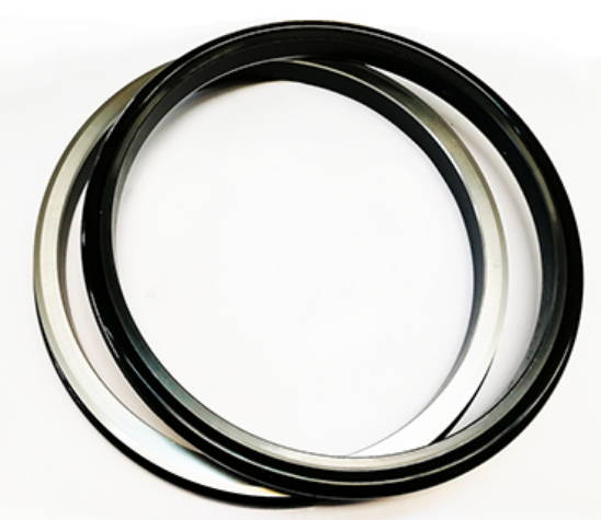
Heavy-duty metal face seals form a distinct group within the broader mechanical-seal field. They are also called floating seals, floating oil seals, duo-cone seals, toric seals, or lifetime seals. They are typically used at relatively low circumferential speeds in abrasive environments rather than as conventional pump-shaft seals.
A metal face seal normally contains two metal sealing rings and two elastomer loading elements. One ring is installed in each opposing housing. During operation, one ring rotates relative to the other, and the precision-lapped metal faces form the primary sealing interface. The elastomers provide secondary sealing, center the rings, transmit torque, and maintain axial face load.
The design performs two jobs simultaneously:
1. Retaining oil or grease around bearings, gears, or drivetrain components
2. Excluding mud, sand, dust, water, and other external contaminants
Typical applications include excavator and bulldozer undercarriages, final drives, axles, track rollers, tunnel boring machines, conveyors, mining machinery, and agricultural equipment.
The DO type mechanical face seal uses two symmetrical metal rings and two toric O-rings. The O-rings sit between the tapered metal-ring surfaces and the housings. Their controlled compression positions the rings, transmits torque, and maintains sealing force.
DO is a widely used configuration for construction, mining, and agricultural machinery. Installation geometry and O-ring condition are critical. A correctly sized installation tool is normally used to press each half evenly into its housing without twisting the O-ring.
The DF type mechanical face seal uses a diamond- or trapezoid-shaped elastomer instead of a round O-ring. Compared with a conventional DO configuration, the DF profile can require less axial installation space and permits a relatively straightforward housing contour. A dedicated installation tool is generally not required, although cleanliness, even seating, and correct housing dimensions remain essential.
DF seals are used in many of the same severe-duty environments as DO seals. The two types are not automatically interchangeable because their elastomer profiles and housing geometries differ.
The XY type mechanical face seal contains two asymmetric metal rings—an X-profile ring and a Y-profile ring—together with two O-rings. The two sides form a matched pair rather than using identical ring profiles.
XY seals are selected when the original equipment or housing has been designed around this asymmetric geometry. Part numbers, ring orientation, installation dimensions, and housing drawings should be verified before replacement.
The YY type mechanical face seal is a compact, housing-specific floating-seal configuration. Like other heavy-duty face seals, it uses metal sealing faces and elastomer elements to retain lubricant and resist contaminant entry.
YY should be treated as a distinct design rather than a universal substitute for DO, DF, or XY seals. Selection requires confirmation of the complete installation geometry, not only the nominal inner or outer diameter.
Seal type alone does not determine service life. Face and secondary-seal materials must tolerate the fluid, temperature, pressure, speed, contamination, and lubrication conditions.
Common face-material combinations in process equipment include carbon, silicon carbide, tungsten carbide, and various hard coatings or alloys. Carbon provides useful self-lubricating behavior in many liquid services, while silicon carbide and tungsten carbide are considered where greater hardness, wear resistance, or chemical resistance is needed. The mating pair must be selected as a system because two individually durable materials can still generate excessive heat or wear when paired incorrectly.
Heavy-duty floating seals often use wear-resistant cast-alloy rings. The material data for the referenced mechanical face seal range specifies high-chromium alloy cast iron at 60–72 HRC. Available secondary-seal materials include NBR, HNBR, VMQ, and FKM. Each elastomer has a different temperature range and resistance to oils, fuels, chemicals, weathering, and compression set.
Material temperature limits should not be used in isolation. Actual seal temperature can be higher than the bulk fluid or ambient temperature because of friction and inadequate heat removal.
The most reliable selection process begins with operating data rather than a familiar part name. Review the following factors.
A centrifugal pump shaft, top-entry mixer, compressor, gearbox, and tracked-vehicle final drive impose very different loads. First determine whether the application requires process-fluid containment, external contamination exclusion, lubricant retention, or a combination of these functions.
Record the process fluid, lubricant, solids content, particle size, concentration, viscosity, lubricity, vapor pressure, and chemical compatibility. External contaminants such as mud, silica dust, wash water, fertilizer, or ore slurry also affect the design.
State normal, minimum, maximum, and transient pressure. For a dual seal, define buffer or barrier pressure. For a floating seal, confirm whether pressure acts from inside to outside or in the reverse direction, because excessive pressure can displace rings or elastomers.
Record shaft speed and calculate surface or circumferential speed at the seal faces when required. A seal suitable for a slow-moving axle may not be appropriate for a high-speed pump, even if the diameters appear similar.
Include start-up, continuous, shutdown, cleaning, and ambient temperatures. Check face materials, elastomers, metal components, and any barrier or buffer fluid—not just one material in the assembly.
Required dimensions may include shaft or sleeve diameter, bore diameter, working height, housing taper, axial gap, gland bolt pattern, and available radial clearance. For DO, DF, XY, and YY floating seals, the existing housing geometry is a primary selection factor.
Shaft runout, end play, housing deflection, vibration, and bearing condition influence face tracking. A new seal cannot compensate indefinitely for worn bearings, damaged housings, or excessive shaft movement.
Consider technician access, the need to remove couplings or bearings, availability of setting fixtures, and the risk of contaminating the faces during assembly. A cartridge or split seal may reduce maintenance time in process equipment. A DO floating seal may require a dedicated floating-seal installation tool to seat the O-ring and metal ring evenly.
For toxic, flammable, volatile, or environmentally controlled fluids, determine whether a single seal is acceptable or whether a dual arrangement and monitored support system are required. Applicable plant rules, equipment standards, and local regulations should be reviewed by the responsible engineer.
| Operating Situation | Seal Type Commonly Evaluated | Reason |
|---|---|---|
| Clean, lubricating liquid in a general-purpose pump | Single mechanical seal | Simple arrangement when controlled leakage is acceptable |
| Hazardous or poorly lubricating process fluid | Dual pressurized seal | Clean barrier fluid separates the process from the atmosphere |
| Process that deposits solids around a sliding O-ring | Non-pusher or engineered slurry seal | Reduces the risk of a sliding secondary seal becoming obstructed |
| Routine pump maintenance where installation consistency is important | Cartridge seal | Preassembled face setting reduces field adjustment |
| Large equipment that is difficult to dismantle | Split seal | Can be fitted around the shaft in suitable applications |
| High-speed or large-diameter rotating equipment | Stationary seal design | Keeps the flexible loading unit from rotating |
| Track roller, final drive, or axle exposed to mud and abrasive dirt | Heavy-duty metal face seal | Retains lubricant while excluding external contamination |
| Existing housing with round toric-ring geometry | DO face seal | Matches an O-ring-loaded symmetrical configuration |
| Existing housing with trapezoidal elastomer geometry | DF face seal | Matches the DF housing and secondary-seal profile |
This table is a starting point, not a substitute for application engineering. Equipment drawings and complete operating conditions should be verified before ordering or modifying a seal.
Several recurring mistakes shorten seal life even when the nominal seal type appears correct:
◆ Selecting by shaft diameter alone
◆ Treating DO, DF, XY, and YY seals as interchangeable
◆ Ignoring short periods of dry running or start-up pressure
◆ Choosing an elastomer only by temperature rating
◆ Failing to account for solids, crystallization, or external abrasive contamination
◆ Reusing damaged housings or shafts without checking runout and surface condition
◆ Installing lapped faces with dirt, fibers, fingerprints, or scratches present
◆ Using oil or grease on an O-ring when the installation procedure prohibits it
◆ Assuming a dual seal will work without the correct support system
◆ Replacing repeated seals without investigating bearings, alignment, vibration, or lubrication
Seal failure is often a system problem rather than an isolated component problem.
There is no single fixed number because mechanical seals are classified in several overlapping ways. Common groups include single and dual, pusher and non-pusher, balanced and unbalanced, component and cartridge, rotating and stationary, and contacting and non-contacting seals. Heavy-duty metal face seals add further configurations such as DO, DF, XY, and YY.
Most mechanical seals use opposing faces, so “mechanical face seal” can be a broad technical description. In heavy-equipment terminology, however, mechanical face seal often refers specifically to a floating seal made from two metal rings and two elastomer loading elements. This type protects lubricated components against severe external contamination and differs from the compact shaft seals typically used in process pumps.
A single seal has one pair of primary faces. A double or dual seal has two face pairs with buffer or barrier fluid between them. Dual seals provide additional containment or a controlled lubricating environment but require more components and a suitable support system.
No. Balanced seals generally produce lower face loading and are useful for higher-pressure or heat-sensitive duties. Unbalanced seals can be simpler and effective within appropriate pressure and fluid limits. The operating data determines which design is suitable.
The answer depends on where the abrasion occurs. A slurry pump may need a purpose-designed slurry seal, hard face materials, and a suitable flush or barrier system. A slow-speed final drive or track roller exposed to mud, sand, and water may require a heavy-duty metal face seal. These designs should not be substituted for each other simply because both applications contain abrasive particles.
Not without validating the housing. DO and DF seals use different secondary elastomer profiles and seating geometries. Even if their nominal diameters are similar, the housing contour, working height, compression, and installation method may be incompatible.
Useful information includes the original part number, equipment model, clear photographs, metal-ring dimensions, working height, O-ring or trapezoid-ring dimensions, housing drawing, lubricant, operating temperature, speed, pressure, and contamination conditions. A worn sample should be measured carefully because wear may alter critical dimensions.
The main types of mechanical seals cannot be understood from a single list because every design combines several characteristics. Arrangement describes whether the seal is single or dual. Loading method distinguishes pusher seals from bellows designs. Hydraulic geometry determines whether a seal is balanced or unbalanced. Assembly style identifies component, cartridge, and split seals. Operating principle separates wet-contacting, dry-running, and non-contacting designs.
Heavy-duty metal face seals form another important category for slow-speed equipment exposed to mud, dust, sand, water, and other contaminants. Within this group, DO, DF, XY, and YY designs differ in ring symmetry, elastomer shape, axial space, and housing requirements.
The correct seal is therefore the design that matches the equipment geometry and the complete operating environment—not simply the type with the strongest material or the most advanced name. Accurate pressure, speed, temperature, fluid, contamination, movement, and installation data remain the foundation of reliable selection.
Previous None
Next Rotary Face Seals: How Heavy-Duty Mechanical Face Seals Work
NAVIGATION
Tel.: 010-80382045
E-mail: sales@bjzhongnuo.com
Wechat: +86 175 0108 8188
WhatsApp: +8615831560503
Add.: No. A48,TiantanDongli,Dongcheng District,Beijing,100061,China
Request a Quote